DIGITAL
interference free data transmission
ADDRESSABLE
an address can be assigned to each device, that can be used to access the device individually
LIGHTING
for lighting systems
INTERFACE
IEC standardised protocol (IEC62386)

About DALI
DALI is a digital light management system that is much cheaper and easier to handle than typical building bus systems such as KNX, Luxmate or BacNet and more flexible in terms of adaptability and configuration options.
DALI replaces analogue 1-10V as well as digital DSI control technology and surpasses them in terms of flexibility and individuality. DALI can be used as autonomous light management system, as well as connected to building automation systems.
DALI Advantages
- The only worldwide standard for professional lighting control.
- Easy installation: the mains voltage and the two DALI control wires can be routed together in the same cable → simplified wiring
- Two-wire wiring: can be installed together with the mains (L, N, PE). The same wiring methods are supported.
- Stable dimming function: digital control signal for all devices → no light fluctuations.
- Flexibility: Each DALI operating device has its own address and can be individually controlled.
- Distributed intelligence: Various operating parameters are stored directly in the DALI operating device (for example, scene value, group membership, fade time, power-on behavior, etc.).
- Status feedback: Request information (defective lamps, brightness)
- Flexibility – Group Concept: A group is a summary of lights. Each operating device can be assigned to one or more of 16 groups, which greatly increases flexibility over non-addressable, rigidly wired systems.
- Flexibility – Scene concept: In each DALI operating device up to 16 different light values can be saved as scene value. This allows the recall of predefined lighting scenes without delay.
- Logarithmic light resolution up to 0.1%: The dimming curve is adapted to the brightness perception of the human eye.
Properties of a DALI system
- up to 64 addressable DALI operating devices
- 16 DALI groups
- 16 DALI scenes
- DALI bus voltage: 12V-22.5V (typical 16V)
- DALI system current: <250mA
- data transfer speed: 1200Baud (asynchronous)
- cable length of up to 300m (1.5mm2 wire cross section), as a result of the maximum voltage drop of 2V on the DALI-line and the system current
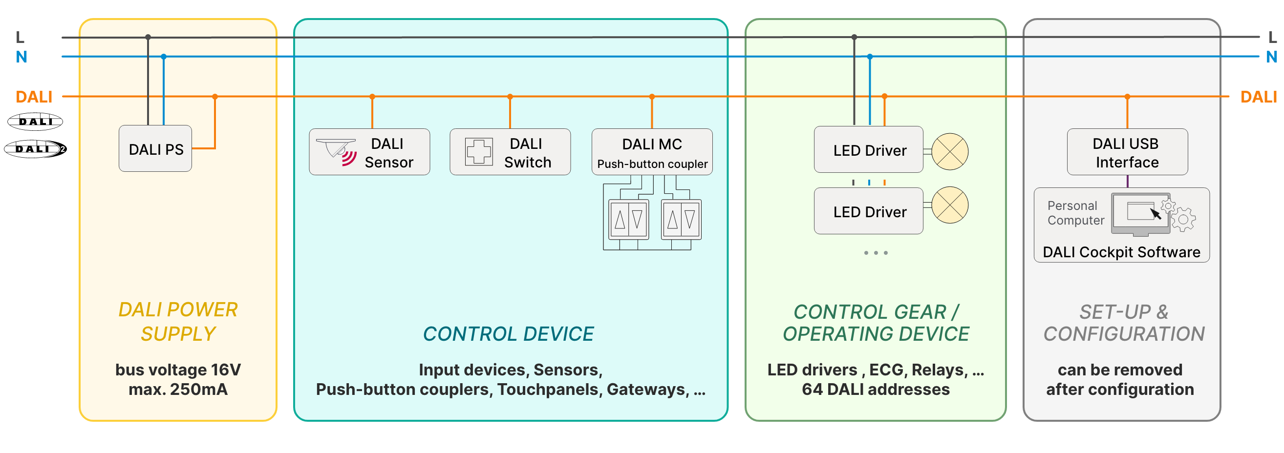
Structure of a DALI system, a DALI system contains the following components:
DALI power supply: each DALI line requires a bus supply.
Control units: user interfaces that send DALI commands to control gear (e.g. touch panels or switches with DALI interface).
Control gear: DALI ballasts (for example LED dimmer) execute received DALI commands according to stored parameters to control luminaries.
The simplest DALI circuit therefore consists of a DALI power supply, a control unit which sends commands and a control gear which executes the commands. This DALI circuit can be expanded with additional operating and control devices.

DALI systems set-up
Simple applications that have no groups, scenes or special functions can certainly be put into operation immediately. However, in order to exploit the full functionality of a DALI system, the operating and control devices should be addressed, grouped and configured once at the set-up of the installation. This is done with the help of the tools DALI USB Interface and DALI-Cockpit Software or with a suitable control device (eg: DALI 7 “Display).
The most important configuration settings for a control gear are:
- assignment to groups 0-15
- scene values 0-15
- fade time
- dimming speed for relative dimming (“fade rate”)
- power up behaviour (“PowerOn Level”)
- behaviour in case of bus power failure (“System Failure Level”)
Same applies to control units, if the function is configurable, changes can either be made with the aid of the commissioning tools or, if provided, via rotary switches or jumpers on the device itself.
Controlling a DALI system - Groups & Scenes
A properly set up operating device can be individually controlled via the DALI bus using the DALI command set. The effective range of a DALI command is defined by the address contained in the command; a distinction is made between individual addresses (“short address”), group addresses and broadcast.
Individual addresses (“short address”)
Unique address for a single device.
Groups
When a device is assigned to a group, it responds to commands sent to that group.
With commands to groups entire areas can be switched and dimmed together.
Broadcast
Command is sent to all devices.
Scenes
16 individual brightness values can be stored as “scene values” in a DALI operating device. These brightness values are set by the device when the corresponding scene is called up. The scene call can be sent directly to the device, to a group of this device or broadcast.